The correct working of the ZENITH Carburetter cap only be .assured when it is not tampered with in any way; the jets must not be reamered out or hammered up, and the hints which are given in this booklet must be strictly adhered to. A ZENITH Carburetter, properly fitted, can be tuned up in a few hours, but when badly fitted the tuning up becomes impossible.
The number stamped under the main jet and compensating jet corresponds as a rule to the bore of the jets in hundredths of m/m., i.e., main jet that is marked 125 has an orifice with a theoretical diameter of 1.25mm.,and one that is marked 85 should measure 0.85 m/m. All jets are calibrated on a B. & B. Mark lI flowmeter, but sometimes customers specially request that the jets should be stamped with the number corresponding to their flow in cubic centimetres of petrol per minute, on the Mark lI flowmeter. In this case, however, the jets are specially marked with c/c after the number, and we shall be pleased to send a list of equivalents to an interested customer.
All the jets are very carefully gauged to pass a certain quantity of fuel in a stated time, and therefore two jets bearing the same number pass exactly the same quantity. It is thus essential that they should not be altered under any circumstances. The standard markings on our jets run in fives, so that a size larger jet than 80 would be 85, and a size smaller 75, and so on. The higher the number the larger the jet.
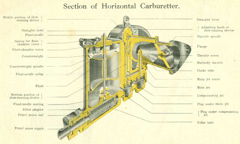
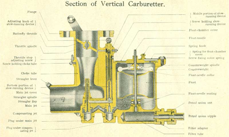
For the names of the different parts of the Carburetter, please refer to the sectional drawings on pp. 14 and 15.
NATURE OF THE FUEL USED
The ZENITH Carburetter is supplied already adjusted for use with petrol spirits of densities between 700° and 750°. Carburetters thus adjusted may therefore be used with benzole without altering the setting. The level, however, will be lower in the Carburetter owing to the increase of density, but this difference in level is necessary and precludes, as a rule, any modification of the jets. Never weight the float or make alterations to the level when using heavy spirits, but one size smaller jets may often be used to advantage.
It is of the utmost importance when using comparatively high density spirit, such as Benzole, to install a very efficient heating apparatus in order to properly vapourise the heavier fuel. Paraffin can also be employed with the zenith Carburetter providing an efficient vapouriser is fitted between the carburetter and the cylinders, and arrangements are made to run the engine until hot on petrol, when it can be switched over to paraffin. The secret of success with paraffin is to properly vapourise the fuel, and in this respect it may be said that a proper vapouriser is one in which the inlet pipe virtually passes inside the exhaust pipe.
FITTING THE CARBURETTER
POSITION: The vertical type of Zenith Carburetter must be placed in an accessible position in order to be able to quickly take out the jets and unscrew the petrol union. A space of a few inches should therefore be left below the carburetter, which, however, should be placed sufficiently low in order to ensure a plentiful supply of petrol, even when the car is on a steep hill. As a rule, the bottom of the petrol tank should be at least * inches above the top of the float chamber.
For cars on which the tank is placed under the seat, it is of course necessary to place the carburetter fairly low down. It is always preferable to place the float chamber towards the front of the car so that when going downhill the petrol does not run out of the jets. These precautions are of course not necessary for the horizontal tyoe of carburetters, as these can only be fitted in one position, and that is against the inlet port on the cylinder. Their accessibility is therefore assured, but on the other hand they can only be fitted to cars where the petrol is supplied under pressure or by vacuum tank or where the tamk is sufficiently high on the dash. These horizontal carburetters are only suitable for monbloc engines having one inlet port, with the valves on the opposite side. If an inlet pipe is used, the vertical carburetter is more suitable, and this type only must be adopted. Also take care to see that the carburetter is fitted quite horizontally, so that when the car is on level road the carburetter is also quite level and does not slope one way or the other.
CONTROL: The control, being worked by the accelerator pedal or by a lever on the steering wheel, should be as direct and rigid as possible. It should be arranged in such a manner that the complete movement of the accelerator or hand lever corresponds to the complete movement of the throttle lever on the carburetter. It is also advisable to so arrange the controls so that a large movement of the pedal or lever corresponds to a small movement of the throttle lever on the carburetter. This gives a greater flexibility of control.
Stiffness must be avoided, so that when acceleration is effected by the pedal and the latter is then released, the throttle in the Carburetter will return to its former position. In addition to the accelerator pedal spring, it is desirable to fit another small spring on the throttle lever itself in order to take up any slackness or play in the connections. The later types of Zenith Carburetters are fitted with adjustable throttle levers which enable them to be set in any position.
CONCERNING THE INLET PIPE
The shape, size and disposition, of the inlet pipe are most important factors to be taken into consideration when fitting a vertical Zenith Carburetter. The internal diameter of the horizontal branch leading to the cylinder ports can be of the same size as the ports themselves, but the vertical portion should be tapered from a few millimetres smaller than the outlet of the Carburetter to the same size as the branch.
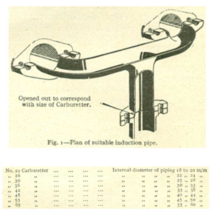
Fig 1 shows a sketch of a well-designed inlet pipe. We have found the following sizes of piping (internal dimensions) the most suitable for the various Carburetters of our make. Sudden. changes in the speed of the gas cause a considerable loss of charge, and it is therefore necessary that internal variations of size should be progressive. It was formerly thought necessary to have pipes of equal length to go from the Carburetter to the different cylinder ports.
Experience has, however, demonstrated that pipes of different lengths had very little influence on the filling of the cylinders, but that bends were the cause of a considerable loss of charge. We give below (Figs. 3 and 4) two examples of well-designed piping, and Fig. 2 shows a pipe which, although serving the same purpose, gives inferior results.

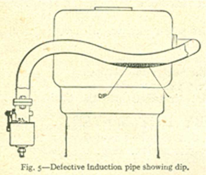
Dips and pockets in which petrol vapour can condense should also be avoided (Fig. 5)
If the piping is to branch off in order to distribute the mixture to several cylinders, this branching should occur at not less than 3 or 4 inches from the Carburetter, Drawn copper inlet pipes are much better than cast ones, as with the latter the internal surface is rough, which restricts to a certain extent the free flow of the gas. These remarks also apply generally to the inlet passages inside the cylinder block, when a horizontal Carburetter is employed. The general layout of the inlet pipe or passages from the Carburetter to the valves should always correspond as near as possible to the conditions laid down.
In order to facilitate the task of making induction pipes, we have introduced a series of flanges, bends, T pieces, etc., which will render the fitting of the vertical type of Carburetters quite easy. Particulars will be sent on application, whilst our copper-smithing department are always in a position to make complete pipes or special fittings.
We also always carry in stock a large number of special inlet pipes, adaptors, etc., to enable the Zenith Carburetter to be efficiently fitted to many well-known makes of cars.
HEATING
The horizontal type of Carburetter does away. with the need of a heating device, as it can only be fitted where there is a certain length of induction pipe inside the cylinder casting, which is heated by the water circulation.In order to ensure the perfect working of the vertical Carburetters, the air entering the Carburetter, or better still the mixture itself, must be heated.
It is impossible to correctly tune up a vertical Carburetter which does not possess one or the other of these heating systems, and the majority of the difficulties encountered by our customers in tuning up their engines are caused by the absence of, or the inadequacy of, the heating device.
These difficulties are caused by the condensation of the petrol vapour in the induction pipe, and it is indispensable that this condensation should be avoided in order to be able to regulate the slow running, ensure a quick pick-up, and obtain an even running of the engine. This is a very important point, and we wish to particularly bring it to our customers' notice.
There are three methods of heating:
1. By means of the water circulation.
2. By means of the exhaust gases.
3. By means of the hot air taken into the carburetter
HEATING BY HOT AIR ENTERING THE CARBURETTER
This system, which should only be used when the water circulation is by thermo-syphon, consists of leading into the Carburetter air that has been warmed by contact with the exhaust pipe. This is effected by placing a muff round the exhaust pipe, from which muff a pipe is taken to the air port on the Carburetter. In certain cases the hot air may be taken from the enclosed space around the valves as shown in Fig. IO, but this method is not very efficient, and should only be adopted when it is impossible to employ any other system.
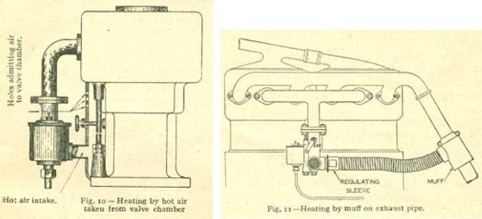
Fig. II shows the best method of heating by means of hot air and we can supply all the necessary parts for this fitting.
Avoid using too long a pipe, and see that the air has not to descend in order to get to the Carburetter. To regulate the quantity of hot air, a revolving sleeve is placed on the pipe just before it reaches the Carburetter. This sleeve has slots cut in it which correspond to slots cut in the pipe, thus enabling cold air to be admitted at will.
FIXING THE CARBURETTER AND FLANGES
If the inlet piping is very rigid, the Carburetter can be suspended from it by means of two bolts. However, if the induction pipe is neither very short nor very rigid, and the Carburetter has. a tendency to shake about, no matter how little, then it must be supported in some way. This support could be fixed at one end by one of the bolts passing through the flange, and at the other end by one of the bolts on the engine or frame.
The flange washer, of fibre, asbestos, etc., should be of even thickness so that the flanges fit snugly together and allow no air to pass in between them. The same remark applies to all joints in the piping.
THE PETROL PIPE AND FILTER
The petrol pipe: It is absolutely necessary to have a filter somewhere on the petrol pipe between the main tank and the Carburetter in order to prevent the jets becoming stopped up with impurities that may come through with the petrol.
To this end our latest Carburetters are fitted with a gauze filter under the float chamber of the Carburetter, and whilst this filter is of very great use, owing to its size and employment of gauze it cannot be perfectly efficient
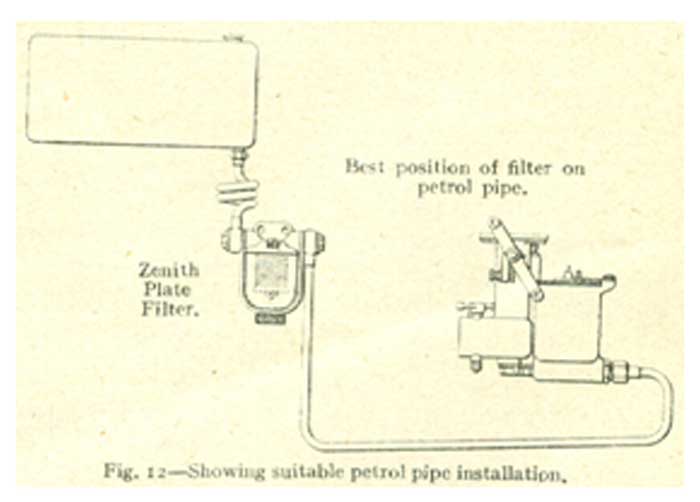
That is why we have placed on the market our new plate type of filter, which will fit between the Carburetter and the tank. This will absolutely remove all impurities from the petrol, definitely preventing the jets becoming choked up under any circumstances. Details of this filter will be gladly sent on application. When the petrol is fed by gravity from the main tank or from a vacuum tank from the Carburetter, care should be taken that the petrol pipe should slope gently from the tank to the Carburetter. There should be no ups and downs, or sharp bends or pockets, in which air would be likely to collect and cause an air lock. The petrol pipe should not touch anything hot, such as the exhaust pipe or silencer, as this would cause the petrol to vapourise and cause a gas lock in the petrol pipe. The petrol pipe should also not touch any parts of the chassis, only where it is necessary, as the constant rubbing against anything hard is liable to wear a hole in the pipe. It is generally advisable to put a twist in the pipe, so as to allow for vibration between the Carburetter and the tank. A well-laid-out petrol system with filter is shown in Fig. 12.
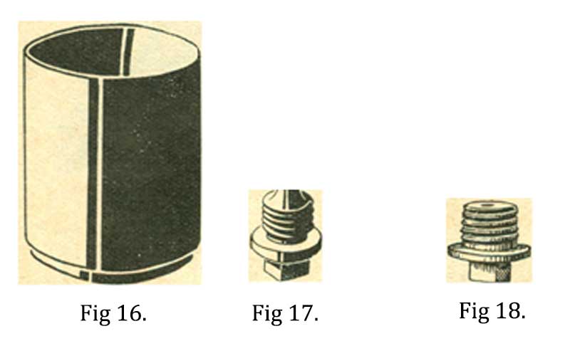
In order to clean the gauze filter under the float chamber, the petrol pipe is first of all disconnected and then the brass hexagon unscrewed from the Carburetter by an ordinary spanner. When this hexagonal adaptor has been completely unscrewed and withdrawn from the carburetter it will bring with it the filter tube, which should be thoroughly cleansed by washing in petrol, taking care not to damage the gauze. It is replaced in the Carburetter in a similar manner.
THE AIR STRANGLER
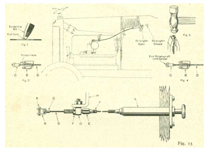
The later models of Zenith Carburetters are fitted with an air strangler, the purpose of which is to facilitate starting when the engine is cold. This strangler should be connected to the dashboard by means of a rod or wire, but very often a Bowden wire is employed.
Great care, however, should be taken in its installation to ensure that when the control on the dashboard is released the strangler on the Carburetter will fly open to the fully opened position. Stiffness in the control will cause a air strangler to stick in a partially closed position, which will upset the general running of the car and increase the consumption. The strangler is only useful for starting purposes when the engine is cold, and must not be used as an air adjustment when the car is running on the road. The correct use of the strangler is described a little later on under the heading " Starting." We give below the method of connecting up the Bowden wire control to the strangler, using the dashboard control that we supply.
TAKING DOWN THE ZENITH CARBURETTER
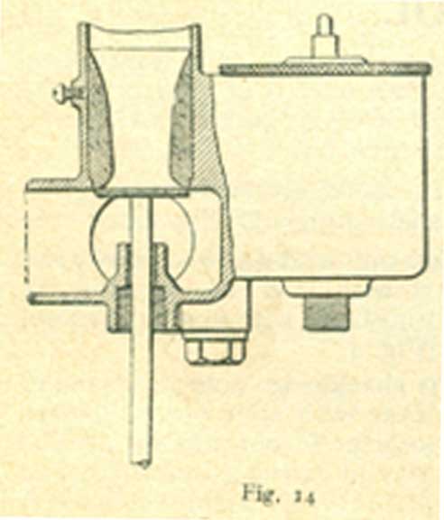
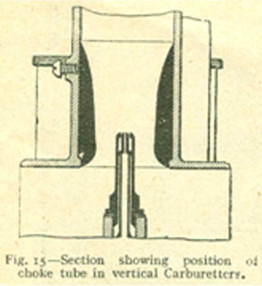
TAKING OUT THE JETS
Section of Vertical Carburetter
TUNING UP THE CARBURETTER
STARTING UP
SLOW RUNNING
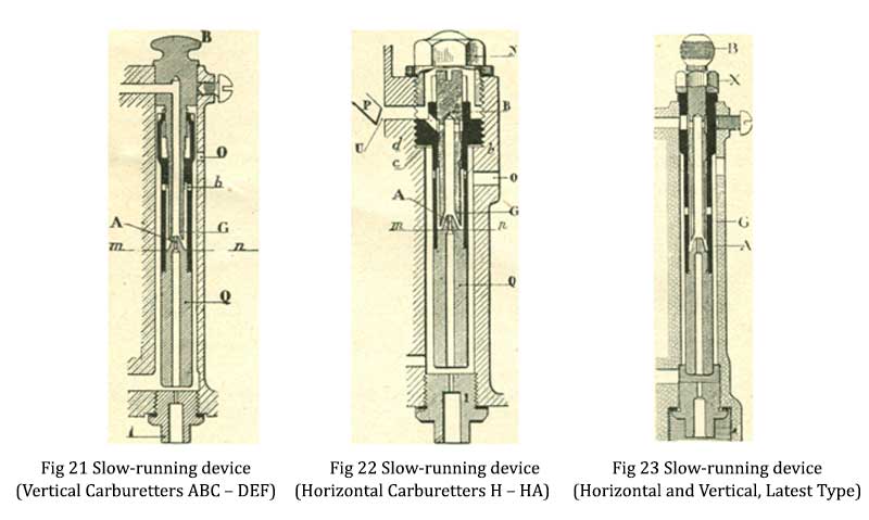
The slow-running tubes, Figs. 21 and 23, are only pushed into the Carburetter and held by means of a screw. Consequently, to remove same, it is only necessary to loosen the screw and pull the tube out. If it is rather tightly fixed the tube can be prised up by means of a screwdriver, the point of which is inserted under the knob “B" or under the nut " X " when this is loosened and using some convenient part of the Carburetter, such as the throttle boss, as a fulcrum.
In the type Fig. 22 the tube is screwed into the Carburetter and has to be removed by means of a special hexagonal key that is supplied with the Carburetter. The method of regulating the strength of the mixture with the slow-running tube is by altering the relative position of the male and female cones "A" and "G."
The male cone "A" takes the form of a conical jet. It will be readily understood if the female cone "G" is put close to this jet, the suction on same will be greater and consequently a richer mixture will be given by the slow-running tube. If, however, the adjustment portion "G" is unscrewed the distance is increased between "A" and "G" and the suction on the former will become less, and naturally the mixture will be weaker.
The size of the male conical jet "A" is stamped on the bottom of the tube, and if it is found that with “A" and "G" screwed close together the mixture is still not rich enough, then a larger orifice "A" is needed, and this can be supplied. Likewise, if with the adjustment unscrewed two or three complete turns the mixture is still too rich, then a smaller jet is necessary.
In the type as per Fig. 2I it is necessary to remove the complete tube from the Carburetter, when the part "Q" can be unscrewed or screwed up. Holding the part “ B" in the left hand and screwing the part " Q" with the right hand in a clockwise direction makes the mixture richer, and anti-clockwise weaker. With the type Fig. 22, which is only employed with horizontal Carburetters, it will be necessary to first of all remove the cap "N," and then turn the screw "B" to the left or right by means of a screwdriver.
The same direction applies, i.e., clockwise-richer, and anti- clockwise-weaker. In the latest type, as per Fig. 23, the adjustment can be made whilst the engine is running by means of the knob "B" After loosening the nut "X" the knob is screwed in a clockwise direction to make the mixture richer and vice versa, then when the correct position has been found, can be locked in place by means of the nut "X"
There is no standard position for the adjustment of the slow- running tube as this varies on each engine, but as a rule it is somewhere between the fully closed position, which is when the female cone touches the male cone-which, of course, is the richest position and two complete turns unscrewed. After the slow-running tube has been adjusted it may be necessary to make another small adjustment to the stop screw on the throttle lever.
GENERAL RUNNING
In the following pages we deal specifically with certain defects in the running, and their remedies, but the following general remarks on tuning will no doubt be useful.
Choke Tube too Large: The effect of this, as a rule, is that acceleration is generally bad under all conditions.
Choke Tube too Small: In this case the engine will generally pick up very well, but maximum speed cannot be obtained owing to the choke tube restricting the quantity of air entering the Carburetter.
Main Jet too Large: This, as a rule, causes the petrol consumption to be heavy, the running to be woolly and irregular at medium and high speeds. It is sometimes found that the same speed is obtained with two jets of different sizes, and the smallest should always be chosen on the score of economy.
Main Jet too Small: This will cause a loss of power and popping back when accelerating. The engine will also run harsh and perhaps a little on the warm side.
Compensating Jet too Large: will cause sluggish acceleration and woolly running at low speed.
Compensating Jet too Small: will cause missing on acceleration, and possibly knocking when pulling hard at low speed.
HOW TO WRITE FOR PARTICULARS RE: TUNING UP
It is absolutely essential to give the following particulars:
1. H.P make and year of car.
2. Number of cylinders.
3. Bore and stroke of same.
4. Number of Carburetter used (please mention all letters and figures stamped on the SIDE of the float chamber)
5. The present setting (number on main jet, compensator and choke tube).
6. Whether a heating device is installed, if so, of which type.
Also please state any other particulars which are likely to help us when replying, such as existing troubles if any.
COMMON RUNNING TROUBLES AND THEIR REMEDIES.
DIFFICULT STARTING WHEN COLD.
Chiefly caused by the throttle not being set in the correct position.
An engine is most easily started from cold in the following manner: Close the air strangler, shut the throttle right back to the stop screw, i.e., the position in which the engine runs slowly out of gear when warm, and then with the ignition switched off, crank the engine over half-a-dozen times or so either by hand or with the self-starter. Then open the throttle between a 1/16th to an 1/8th of an inch, and still keeping the strangler shut, switch on the ignition. It will then generally be found that the engine will start quite readily. The object of cranking the engine over with the ignition off is two-fold, In the first place it frees the engine, and in the second place primes it with suitable mixture for starting.
The best position is generally with the throttle open a shade more than the best slow-running position when warm. A few trials will generally show the best position of the throttle for easy starting, and a mark should be made on the hand control so that the throttle can always be put in this position. In very cold weather starting is sometimes facilitated by slightly flooding the Carburetter.
No Air Strangler fitted or existing one not closing properly: We can supply a loose strangler for fitting to earlier types of Carburetters See that the strangler control permits the complete closing of this.
Slow-Running Tube choked up: Thoroughly clean out the Jet "A" as shown on page I9.
Slow-Running Tube adjusted too weakly: Turn the adjustment knob in a clockwise direction to give a richer mixture.
Air Leakage between Carburetter and Cylinders: Go carefully over all inlet pipe joints, valve caps, sparking plugs, etc. The inlet valve guides may be worn and allowing air leakage between the stems and the guides.
Magneto Retarded too much, or Inefficient at low r.p.m: This must be carefully checked.
Sparking Plug Points too far 'apart: Very often putting these slightly closer together greatly improves starting.
DIFFICULT STARTING WHEN HOT
Slow running tube adjusted too richly: Adjust the knob in an anti-clockwise direction.
Carburetter has been flooded or air strangler closed: An excess of petrol will cause difficult starting when the engine is hot
Throttle not open sufficiently: Adjust the stop screw to open the throttle a shade more
BAD SLOW RUNNING
It is presumed that the slow-running tube and stop screw have been carefully adjusted in accordance with the remarks on page 18, but slow running is still bad.
Air leakage between carburetters and the cylinders: Go over the points mentioned above. If vacuum-tank, servo brake or windscreen wipers are fitted, go carefully over the air connections.
The magneto is inefficient at low speeds or advanced too much: Have this properly examined.
Plug Points too far apart: Try these with a slightly smaller gap. Inlet Valve Tappets badly or unevenly adjusted.-Very carefully set these.
Uneven Compression in Cylinders: Have the valves ground in, etc.
Inlet Pipe or Passages not sufficiently heated: When the engine is running slowly, the petrol vapour will condense on the inside of the unheated passages, causing irregular slow running. Improve the heating by fitting a hot air pipe or cleaning out the jacket if one exists.
Throttle Spindle or Throttle Worn: After a number of years of use, the throttle spindle and throttle wear, which may upset the slow running. In this case it is always best to send back the Carburetter to be thoroughly overhauled and made as new, for which we have a prompt and efficient repair department.
Engine stops of its own accord after running slowly for a certain time: Where a vacuum tank is employed it is sometimes found that each time the vacuum tank functions, the engine stops.
This is due to a charge of rich gas being drawn from the autovac tank through the suction pipe, thereby upsetting the mixture supplied by the Carburetter. Also, where a Servo brake mechanism is employed it will often be found that the engine will be liable to stop when the brake functions. Obviously there is no cure for
either of these two things by Carburetter adjustment.
ENGINE STOPS ON DECELERATION
Slow-Running Tube choked up: Take out and clean.
Slow-Running Tube adjusted too weakly: Set this to give a richer mixture. •
Inlet Valve Tappets unevenly adjusted: These must be very carefully set.
Throttle, loose on its Spindle: Take the Carburetter down and tighten the locking screw which holds the throttle to the spindle.
Stop Screw on Throttle Lever improperly adjusted: Set this screw so that the throttle always returns to the best slow-running position.
ACCELERATION IS BAD OR THERE IS HESITATION IN PICKING UP SPEED.
Inlet pipe or passages insufficiently heated, so that when the engine is running slowly petrol vapour condenses on the inside, and when the throttle is opened for acceleration this liquid petrol is sucked into the cylinders, causing' the mixture to be too rich, and hesitation occurs. Arrange to more efficiently heat the inlet pipe or passages.Compensating Jet too large or too small: Try different sizes of compensating jets.Choke Tube too large: Try one size smaller choke tube without altering the jets.Slow-Running Tube not correctly adjusted: Very carefully set this as described on pages 18 and 19 to give the best mixture for even slow running. It is sometimes preferable to set the engine to run a shadefaster than is absolutely necessary out of gear as this will sometimes give a cleaner pick-up.Uneven Distribution of the Mixture: Due to the shape of the inlet pipe or passages


