FITTING
The M. and M.O. Solex are made in both vertical and horizontal types. The vertical we denominate M.V. and M.O.V. These types are generally employed in the case of engines having an external induction pipe.
The horizontal models are termed M.H. and M.O.H., and are for monobloc engines, with an internally cast induction system and one inlet port. This adaptation is made directly to the cylinder block, provided the head of petrol is sufficient to supply the carburettor, regardless of the inclination of the car. These models have the advantage of being free from external hot air pipe, etc.
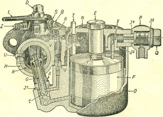
The sectional diagrams appearing on the following pages illustrate the type M.O.V. (Fig. 1) and types M.O.H. (Fig. 2), M.V. (Fig. S).
The internal construction of the M.H. is similar to the M.V., the difference, of course, being one has a vertical takeoff, whereas the other is designed horizontally. The same remarks apply to the M.O.V. and the M.O.H. models which are illustrated on pages 2 and 3.
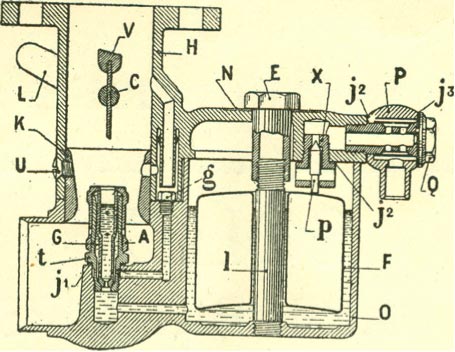
| DIAGRAM NOTATION | |
| A Main jet cap | I Central pillar |
| C Throttle spindle | L Throttle lever |
| E Dismounting spindle | N Name plate |
| F Float | O Float chamber of carburettor |
| g Auxiliary jet | p Needle |
| G Main jet | P Body of Filter |
| H Body of carburettor | Q Filter Union Assembling Nut |
| j1 Main Jet carrier washer | t Main Jet Carrier |
| j2 Needle valve and filter washer | U Choke tube fixing screw |
| j3 Washer for filter union | V Throttle |
| K Choke tube | X Needle valve seating |
Heating In modern engines It is not, as a rule, necessary to apply hot air to the carburettor, for induction manifolds are almost invariably provided either with a hot spot or some form of jacketing.
In cases, however, where there is inadequate heat we can provide a special exhaust pipe muffle and flexible tubing to deal with the question of heating. It is necessary when applying this, or an equivalent device, to be very careful to have absolute freedom of hot air ingress, for any stricture at this point will rob the engine of power.
Air Strangler: To assist when starting from cold. we fit to all M. and M.O. types a suitable air strangler device.
| DIAGRAM NOTATION | |
| A Main jet cap | I Central pillar |
| B Throttle limiting screw | N Name plate |
| D Throttle Spindle end nut | O Float chamber of carburetter |
| E Dismounting nut | P Swivelling filter union |
| F Float | Q Filter union assembling nut |
| G Main jet | R Air regulating screw |
| G Auxiliary Jet | r Tickler spring |
| H body of carburetter | S Throttle abutment plate |
| J1 Main jet carrier washer T Tickler | T Tickler |
| J2 Needle valve and petrol union | t Main jet carrier |
| Washer | U Choke tube screw |
| J3 Large Swivelling union washer | V Throttle spindle |
| J4 Small washer for swivelling | W Filter gauze |
| Union | X Needle valve |
| K Choke tube | Z Slow running adjustment screw |
| L Throttle lever | |
DISMOUNTING THE CARBURETTOR
In order to dismount the carburettor it is only necessary to unscrew the large nut centrally placed on the top of the float chamber, when the latter can immediately be withdrawn, giving free access to the float and both the jets.
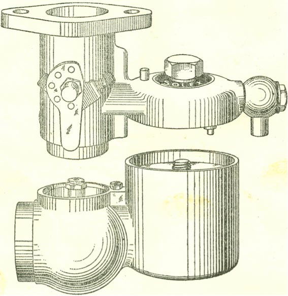
When remounting, it is only necessary to note that the parts register with one another when the nut can be retightened. Access to the jets is perfectly simple. The main can be withdrawn by unscrewing the cap over same, when it can be lifted out, and the auxiliary may be similarly unscrewed with a small spanner or screw driver.
ADJUSTMENT
The adjustment of the Solex has been determined in advance on most of the leading makes of engines, and it is, therefore, generally possible to supply them with a standard combination of choke tube, main jet and pilot jet, which will give the desired results for specific engines, without modification.
The type of carburettor IS recognised by the lettering and numbers stamped on the outside of the float chamber. The first number indicates the size of the carburettor (26, 30, 35, etc.). The letters which follow these two digits confirm the type, i.e., M.V., M.O.H., etc. The figures below are the works number of the instrument, which enables us to trace the identical carburettor in cases where queries are put to us.
In the horizontal design, it will be noted that sometimes the letter 0 follows the initials M.H., and on other occasions the letter G is inserted. F or guidance, we would explain that 0 indicates the float chamber is on the right-hand side when you are looking at the air intake, and G on the left-hand side when looking at the air intake.
The setting of the carburettor is verified by the numbering on the jets and choke tube.
The auxiliary jet (g) is stamped on the top, while the main jet can be withdrawn after removing the jet cap, and the number will be found stamped on the top in the case of the M. type carburettor, but in the M.O. types the marking is generally round the main stem. With M.O. type main jets there is also an additional figure which follows the size, e.g., 100 x 51. The second number indicates the correction and the disposition of the lateral holes.
The choke tube (K) surrounds the main jet and the size is stamped on the inner rim. The first figures confirm the size of the carburettor, and the second figures the choke tube measurement, i.e., 26-22 would indicate that the choke tube is size 22m/m and the carburettor 26m/m.
The adjustment of the carburettor in general, having been arrived at on ordinary No. 1 spirit, it is advisable, sometimes, to fit a heavier float or decrease by one size the jets, if heavy petrol or benzole is used.
In the case of the 26m/m model Solex, the level can be raised by reversing the position of the float, having the concave side uppermost.
Slight alterations are also necessary in the case of engines that are used in hotter climates than that in which they were originally adjusted, and similarly old and worn engines frequently require a modified combination.
The following paragraphs deal with the diagnosis and remedy 'of troubles.
DIAGNOSIS OF FAULTS
There is never a question of definite failure of the SOLEX carburettor. It is simply a matter of locating errors in the selection of jets and choke tube.
lt is advisable always to carry out adjustments with a definite method and never to do more than one thing at a time, for by such a way it is impossible to determine which detail of adjustment was at fault.
FLOODING
Insufficiently tightened joints: In the Solex carburettor there are four joints:
The jet carrier washer
The needle vavle washer
The two washers of the petrol union
The latter being exterior, they will readily disclose any leakage, but a leakage due to the needle valve being screwed insufficiently tightly into its seating in the upper part of the carburettor, will cause the level to be raised and resolve itself into a drip at the main jet.
The first thing to do when any evidence bf this is observed, therefore, is to verify the tightness of all these four joints.
Grit on the needle seating: This trouble is very often in evidence in the case of carburettors not provided with a filter, especially shortly after being fitted, for in new petrol pipes, which have been annealed and bent, flecks of oxide are often set free which can readily lodge in the seating of the needle and cause flooding.'
Punctured float: In this cases the petrol which leaks into the float increases its weight, and a higher level result, causing flooding at the main jet. In such a case, the best cure is to have a new float.
The eights of the standard floats for 730 spirit are as follows:
33 grammes for 26m/m carburettors
42 grammes for 30m/m carburettors
64 grammes for 35, 40 and 46m/m carburettors
We can provide sepcial benzole floats of which the weghts are as follows:
47 grammes for 30m/m carburettors
70 grammes for 35, 40 and 46m/m carburettors
Checking the level: This is a very simple process in the Solex, One has merely to dismount the float chamber, unscrew the main jet cap, take out the main jet and mount the float chamber again in position with the main jet carrier sticking out at the side. Turn on the petrol, when the height to which it rises can be observed. In the case of ordinary spirit it should be approximately 3m/m from the top. There is no functional disadvantage in having the petrol higher than this, but the above limit is mentioned in order to avoid flooding when the car is left standing on a sharp incline.
Excess of petrol pressure: F or exhaust operated auxiliary petrol tanks or for ordinary gravity feed, 26m/m carburettors are supplied with a needle valve of which the seating is 2m/m, while the 30, 35 and 40m/m carburettors take a needle valve of which the seating is 2.5m/m.
When the head of petrol is abnormal (6 or 8 feet) or when the petrol tank is pressure fed, the buoyancy of the float may be insufficient to keep the needle on its seating against this weight of fuel. This is remedied in the case of 30, 35 and 40m/m carburettors by replacing the standard 2.5m/m needle valve with the smaller one having a 2m/m seating. The latter can be supplied to order.
DIFFICULT STARTING
Shortage of petrol: One should first test for the arrival of petrol in the float chamber by depressing the tickler.
By this means it will be easy to determine whether the float is on the bottom of the carburettor or not. Should the former be the case, verify first that the petrol tap is turned on and that there is petrol in the tank. Finally, by Unscrewing the tank union nut determine whether the pipe work is quite free.
It often happens that when new or when the petrol has been allowed to run entirely out of the tank an air lock occurs. In such a case the pipe must be primed by any convenient means. If it is possible to blow into the main filling aperture of the tank this will generally suffice to remove the air lock.
A vapour lock approximating the above in its effects can also be produced if the petrol pipe passes too close to a hot exhaust pipe.
Level too low: If the specific gravity of the petrol is too high, the level can be so low that starting becomes difficult.
In that case it is advisable to change the float for a heavier one or employ a lighter spirit.
Defective slow running: Check first the adjustment as described on page ten, but if by this means it is not possible to locate the trouble, it is probably owing to air leakage at some point in the induction system, possibly via the inlet valve stems in their guides. In this case use an auxiliary jet one or two numbers larger than normal, being careful not to exceed the size required, for in such a case hunting will occur. When equal results are obtained with the two jets it is generally desirable to use the larger.
Before altering jets it is always wise to see that a partial obstruction is not the original cause.
Strangler not closing properly: It is well to assure oneself that when in the starting position the strangler shutter closes completely. If it does not do so, check over the control generally and adjust same so that when operated from the dashboard the shutter entirely obturates the entrance to the choke tube.
Throttle open too wide or not wide enough: The very strong suction on the auxiliary jet which is necessary for starting, cannot be obtained unless the throttle is almost closed. It should be, in fact, only slightly wider than the normal position for idling.
If, however, the carburettor is flooded when the throttle is so placed, the probable results will be two or three fires, then the engine will stop, but the cure for this is to open the throttle a little wider.
DEFECTIVE OR INSUFFICIENTLY ADVANCED IGNITION
It is well to ensure that, before interfering with the carburettor, the ignition is in order, and not to forget that in the case of the magnetos, it is usual to advance the spark to a fair degree in order to get a sufficiently intense starting spark.
Attention is also necessary to the distributor, high tension leads and sparking plugs, the points of the latter should be separated by .6m/m or .025m/m.
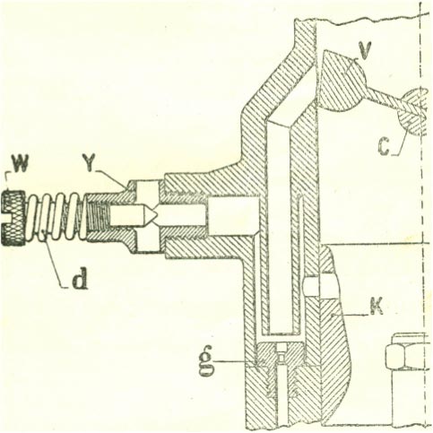
| DIAGRAM NOTATION | |
| C Throttle spindle | V Throttle |
| D Spring | Y Seating |
| g Auxiliary Jet | W Regulating screw |
| K Choke tube | |
SLOW RUNNING
If, in spite of the use of different auxiliary jets, one is still unable to obtain good slow running, a considerable air leakage can be presumed upon almost with certainty, assuming that the ignition arrangements have been verified as correct.
One can generally confirm this by noting the effects of depressing the tickler. Should this slightly speed up the engine it is thereby indicated that air leakage is present to the point where balancing by jet adjustment is impossible, and the only cure for this trouble is to correct the leakage at its source.
Incorporated in the M.O. type Solex carburettor is the air regulating screw" W." The richness of the mixture is determined by this screw, and the rate of idling by adjusting screw “Z," fitted on the abutment plate.
By rotating the air regulating screw “W" outwards, it reduces the strength of the mixture, and, of course, vice versa.
It is preferable, when adjusting the slow running of the M.O. Solex, to commence with the adjusting screw •. W" fully home, this will give the greatest richness, and then gradually unscrewing it until the best performance is obtained.
It is well to make this adjustment when the engine is warm; if attempted when cold, the mixture will be found too weak and starting very difficult (see Fig. 4).
BAD ACCELERATION
One must understand to commence with that it is impossible to expect brisk acceleration immediately after starting the engine, unless one uses an excessively heavy mixture that will be very extravagant and also cause sluggishness directly the engine becomes warm. A certain amount of patience, therefore, is necessarily called for, especially in the winter.
Defective adjustment: Try one Size larger main jet. Verify from the tables that the choke is of a reasonably correct size for the engine in question. If the larger jet has not the desired effect, replace then the original one and try one size smaller choke tube.
Defective ignition.-A feeble spark is a most frequent cause of bad pick-up, and misfire would, in such a case, always be noticed on suddenly accelerating. It is very necessary, therefore, to assure oneself both as to the efficiency of the spark and the condition of the plug points, otherwise, on suddenly opening the throttle, the electrical pressure will often fail to bridge the gap under the resistance of the higher compression resulting from the suddenly opened throttle and low magneto speeds.
In the case of battery Ignition one should be certain that the batteries are not discharged.
If there is a total absence of pick-up and the engine stops directly upon depressing the accelerator, the stoppage of the main jet is indicated.
INSUFFICIENT SPEED ON THE LEVEL
Bad adjustment: Dismount the carburettor and verify the choke and jet sizes as per the instructions already given.
Butterfly not opening sufficiently: Verify that when the accelerator pedal is fully depressed the butterfly is completely open. This can easily be confirmed by noting that the limit screw on the abutment plate is in contact with its stop when the pedal is down.
Insufficiently advanced ignition: Check firing point of magneto when fully advanced, and should this be found insufficient as per the instruction book issued by the manufacturers, it would be well to seek professional advice on the point.
Shortage in fuel supply: lf, after driving for a short distance fairly hard, there is a sudden sensation of power loss coupled with firing in the carburettor, this will generally indicate that the petrol supply is insufficient, especially if there are several reports heard from the silencer on the car over-running the engine.
It is easy to verify the supply by removing the Boat chamber and temporarily turning on the petrol tank. Should one have any doubts as to the sufficiency of petrol head it might be well to make a test with a specially small tank mounted about 2ft. above the carburettor. This will serve to confirm, or otherwise, the adequacy of the ordinary petrol head.
Incandescent plug points will give almost identical symptoms. If, therefore, a shortage of petrol cannot be located, in such a case, examine carefully the plugs. Should the central electrode have a dry and rusty appearance, incandescence is almost certain, and the plugs should be substituted for a new set of recognised heat-resisting qualities.
Choked silencer: After a considerable period it occasionally happens with certain designs of silencers that a partial blockage by soot can occur. It is generally easy to distinguish the onset of this trouble by noting the sound of the exhaust at the back. As choking progresses the explosions become less and less marked, and merge into a steady rush of hot gas instead of clearly marked impulses. Where this is suspected of being the cause of power loss, it is well to make a short test with the exhaust-pipe uncoupled from the silencer.
OVERHEATING
The carburettor is rarely to blame in such a case, the cause being almost invariably due to defective water-cooling arrangements.
It is true that extreme excess of petrol will cause slight overheating, but its effect upon the fuel consumption will generally serve to expose this cause long before one has time to complain re overheating.
Another very frequent factor in this trouble, is unduly retarded ignition, which will always overheat the engine.
Knocking: There are also a very great number of different causes for knocking, and it is almost invariably the result of factors quite apart from carburettor adjustment, such as, defective combustion head design, excessive carbonisation, excessive ignition advance, defective cooling, inferior fuel, and looseness in the pistons or big ends.
If the knocking is actually due to carburation, it always arises from a weak mixture, and is 'curable by a slightly larger jet or a slightly smaller choke tube. Should neither of these alterations effect any improvement, the cause must be sought for elsewhere.
EXCESSIVE CONSUMPTION
Please note there is no leakage at any point of the petrol system. It is then well to verify that the estimation of the m.p.g. has been correctly carried out.
The test, for instance, should be over a definite distance as determined by milestones, or a speedometer that has been carefully checked beforehand.
A special test tank can be adapted, and is preferable for this purpose. We can supply pint and quart size test tanks from stock.
Jet Cap Loose: If the heating is correct and the main jet is as small as possible to give the required power, excessive consumption cannot in the ordinary way be caused by the carburetter, unless the main jet has not been screwed down properly on its seating. In the latter event tighten down the cap, and carry out a further test.
Defective strangler fitting: Please check that the strangler shutter opens fully when released.
Retarded Ignition: This is frequently a case of bad consumption. It is always advisable to keep the ignition as far advanced as possible consistent with the avoidance of knocking. Note also there is no misfiring, for this constitutes a very considerable effect on the m.p.g
Bad condition of the engine: The condition of the motor has, of course, a very considerable effect on the m.p.g. It is easy to understand that if the rings or valves are defective and the compression poor, one not only suffers by the wastage of live charge during compression, but also by loss of the explosion effort during the firing stroke. A combination of these two, especially in the engine which is in other respects not in good condition, could easily double the normal fuel consumption, in addition to which there would be considerable power loss.
After having such troubles remedied, one must remember that the “characteristic” of the engine will be considerably altered, and the carburetter therefore, must in such cases be re-adjusted.
TROUBLES DUE TO SUCTION-OPERATED AUXILIARY
A great many motors are now provided with devices of this description that can frequently cause troubles for which carburation is blamed.
1. Any leakage of air into the suction pipe can cause difficult starting and bad slow running.
2. It occasionally happens that, owing to a defective valve in the suction system,neat petrol can be drawn into the manifold, and when this occurs, the consumption can easily be excessive without any apparent carburation cause.
3. When driving fast up a long hill which requires full throttle, starvation can be caused through there being insufficient depression at the full throttle position to draw fuel from the main tank into the auxiliary reservoir.
In order to confirm this as a possible cause, remove the suction pipe temporarily, block up the induction pipe nipple and treat the apparatus as a test tank.
If the troubles are not reproduced while petrol remains therein, the carburettor has obviously had no part in the original cause.
In such a case, it is' well to apply to the makers of the apparatus.
MECHANICAL PUMPS
These are now fitted as standard on many cars, and fuel waste can result if for any reason too much pressure is being developed. This trouble can generally be presumed when flooding occurs while descending a hill against the engine, and causes fresh petrol to be smelt from the front seats.
If ordinary tests fail to disclose any leakage, a short run with a pint or quart test tank, and the pump out of action, will confirm if the latter is the cause.
There is also a possibility of air leaks between the rear tank and the pump, which will delay the delivery of the petrol to the carburettor.
We supply a pressure gauge set which enables the pump pressure to be tested in situ.
TROUBLES CAUSED BY AIRFILTERS
An air filter with too small a section of filtering medium will frequently raise the consumption owing to the increased vacuum imposed upon the jet thereby. If this is suspected, make a comparative test with the air filter removed. Should the cause be located here, first clean carefully the filtering medium and try again, but if the consumption is still bad, it is probably the result of the filter itself being too small.
IMPORTANT
When communicating with us in regard to your Solex Carburettor it is essential to quote the letters and numbers stamped on the float chamber.
TYPE MV

| DIAGRAM NOTATION | |
| A Main jet cap | I Central pillar |
| C Throttle spindle | N Name plate |
| E Dismounting nut | 0 Float chamber of carburettor |
| F Float | P Swivelling filter union |
| g Auxiliary jet | p Needle |
| G Main jet | Q Filter union assembling nut |
| H Body of carburettor | r Tickler spring |
| i' Main jet carrier washer | T Tickler |
| j2 Needle valve & petrol union washer | t Main jet carrier |
| j3 Large swivelling union washer | U Choke tube fixing screw |
| K Choke tube | V Throttle |
| L Throttle lever | X Needle valve |